Monitoring (Action B1) - The new prototype R3S is ready
The LIFE-Respire remediation system consists of two main components, the radon sensor with its associated control electronics and the ventilation unit for air exchange. Development work has continued on both aspects since our last newsletter, addressing both reliability and effectiveness.
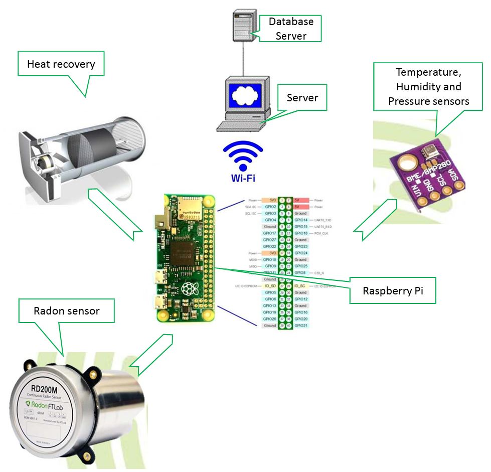
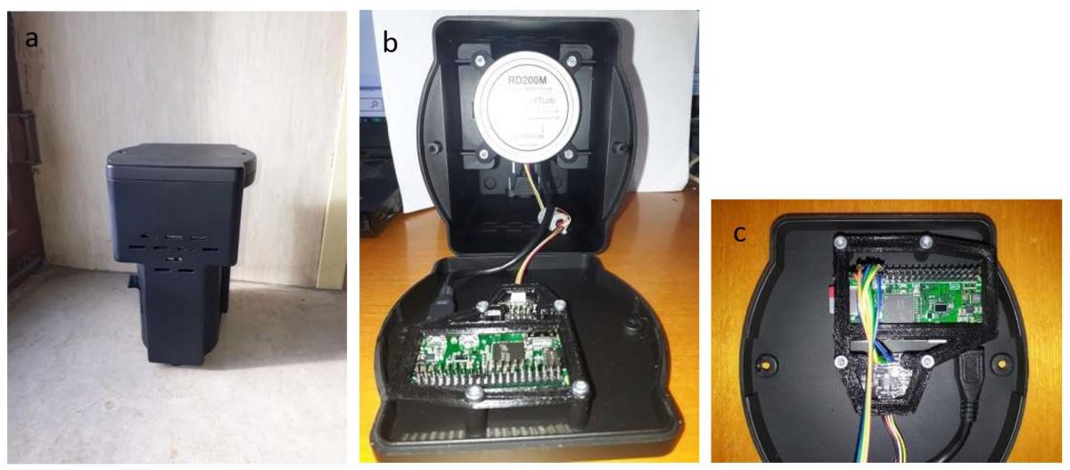
The electronics part of the system has undergone various improvements in the last year, aided primarily by substituting an ad hoc electronic board with a lowcost Raspberry Pi mini computer. This upgrade allowed us to use a well-tested, powerful framework on which to build new capabilities now and for future development. The present version has an internal data logger to prevent data loss if connectivity with the Cloud is temporarily lost, direct Wi-Fi communications to a local hotspot to give the system more flexibility, integrated pressure, temperature and humidity sensors to better monitor air quality, energy efficiency and radon exchange processes, and a more robust computer code (“firmware”) for managing the unit as a whole.
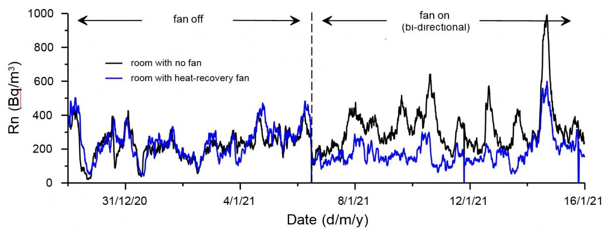
This new generation is presently being tested in 2 sites in Belgium and 2 sites in Italy, with many more ready for installation once the COVID pandemic situation improves and it is possible to access the other test homes and schools. Although the project initially used an extraction fan for ventilation, it was always foreseen to test other types of technologies during LIFE-Respire. Over the last year we have been examining the potential of small heat-recovery and heat-exchange units, particularly in terms of addressing our goals of improving air quality while maintaining a reasonable level of energy efficiency. Heat-recovery units are lower cost but move less air, due to the fact that they have a bi-directional fan that alternates between air extraction and ingress to allow heat recovery via a ceramic disk. The more expensive heat-exchange units, instead, have higher flow rates because the exiting indoor air and the entering outside air are flowing constantly in separate pathways that allow for heat to be transferred. One test we conducted involved installing a heatrecovery unit in a room in a semi-basement, together with radon sensors in this and an adjacent control room. As can be seen in Figure 1, radon concentrations in the test room drop to about half of those in the control room once the ventilation unit is set to bi-direction air exchange. These results are highly promising for attaining the project’s goal of reducing average annual radon concentrations below the legislated level.